


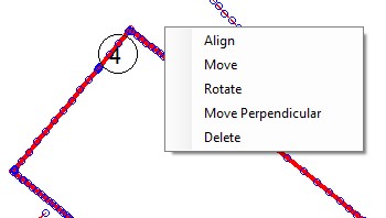
By clicking with the right mouse button on the selected scans (in graphics or in the Hide/Show window) the Contextual Menu will be shown where we find very powerful functions that will allow us to align the scans with each other and correctly reconstruct the entire survey.
With these functions we will be able to both combine scans acquired separately and correct any alignment problems that occurred during the automatic alignments performed with the NextScan functions of the mobile app.
The alignments could also be processed later in CAD, but here we find dedicated functions that will make the task easier.
With this menu you can also delete a scan from the project.
Align
This is a very powerful function that with 4 clicks will align two scans.
Once started, a first origin point and a destination point will be requested and the software will perform a translation to make these points coincide and will assume this position as a pivot for the subsequent rotation, then a second origin point and a destination point will be requested and the system will carry out the rotation.
Both survey points and end points of the Traced interpolated Lines can be chosen, in the latter case the result will be more rigorous.
The feature can also be activated by pressing the spacebar once.
Move
This is a function that with 2 clicks will move the scans.
Once started, a first origin point and a destination point will be requested and the software will perform a translation to make these points coincide.
Both survey points and end points of the Traced interpolated Lines can be chosen, in the latter case the result will be more rigorous.
The feature can also be activated by double-pressing the spacebar.
Rotate
This is a function that with 3 clicks will rotate the scans.
Once started, a base point will be requested and the software will assume this position as a pivot for the rotation, then a start point and end point of rotation will be requested and the system will carry out the rotation.
Both survey points and end points of the Traced interpolated Lines can be chosen, in the latter case the result will be more rigorous.
The feature can also be activated by pressing the spacebar three times.
The Move and Rotate functions used in succession can be used to align scans, but the same result is achieved more quickly with the Align function.
Move Perpendicular
This is another very powerful feature that allows you to translate a scan along a chosen line or perpendicularly to it. Its greatest utility lies in creating partition walls between rooms and aligning doors. To do this, simply follow these steps:
- Use the “Align” command to align the scans.
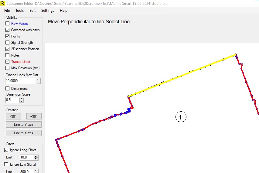
- Start the “Move Perpendicular” command.
- Select the line.
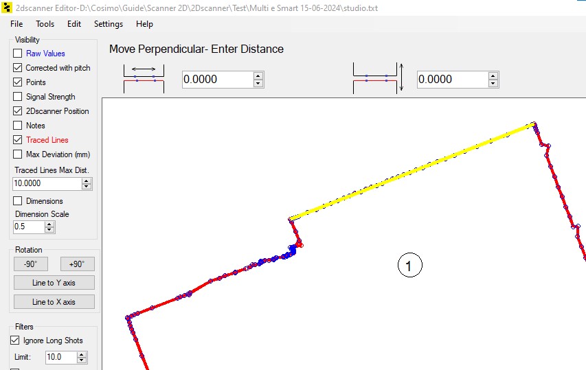
- Align the door by translating the scan along the line using the arrows until the ends of the door belonging to the two scans coincide.
- Create the wall thickness by translating perpendicularly to the line by an amount equal to the wall thickness.
Once the command has been launched, the selection of the reference line is requested. By passing the mouse over the Traced Lines they are highlighted in yellow to facilitate identification.
Once you have chosen the line, click on it. At this point two entry boxes appear where you can enter values or scroll them with the arrows. With the first you will slide the scan along the chosen line to align the ends of the door, with the second you will assign the thickness of the wall and then the scan will move away perpendicular to the chosen line by the assigned value.
Tips – To optimize the use of this function, it is recommended to acquire singular points “Notes” at the ends of the door during the survey and enter the thickness of the wall measured manually at the time in the text field.
Offset Line (Feature not yet active)
This feature can have various applications, but it is mainly designed to graphically reconstruct the exterior walls of the building once their thickness is known.
Therefore, during the survey phase with the mobile app, it is suggested to identify the openings towards the outside with notes and to include in the text the thickness of the infill wall measured manually.
Once the command has been launched, the selection of the reference line is requested. By passing the mouse over the Traced Lines they are highlighted in yellow to facilitate identification.
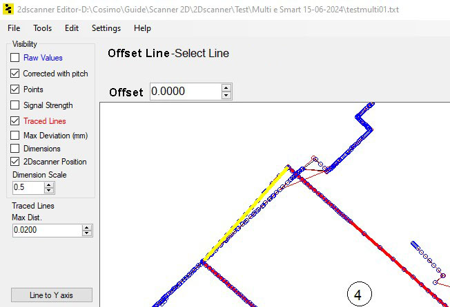
Once you have chosen the line, click on it. The system will request the offset distance, which must be entered in the appropriate box.
Delete
The selected scans will be deleted from the project.