


The File Menu has 6 options.
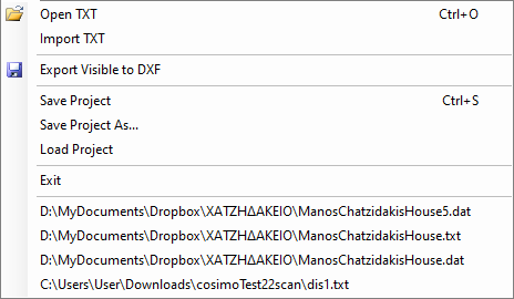
Open TXT
Used to open a TXT file generated by 2Dscanner. This can be done and via Drag n’ Drop. The user can use any unit he wants in the app and it will be automatically recognized in Editor.
TXT it is a text file and the data of all the measured points are saved in it, even those not present in graphics and DXF as they are hidden by the “Ignore Long Shots” and “Ignore Low Signal” filtering functions. Each line of the file will be relative to a point and will contain the following information separated by commas:
- Angular position. (360 degrees=32000)
- Angle in degrees. (It is not position/32000*360. It has a small correction added which is measured during calibration)
- Distance with the offset added from the machine center in mm.
- Pitch angle on degrees. (Inclination angle of the measurement with respect to the horizontal)
- Reading from laser in meters.
- The Signal. (the higher the value the less reliable the measurement)
Import TXT
Used to open a new file TXT and add it to those already present in graphics.
Export Visible to DXF
Exports all the visible elements in DXF format. In the Visibility box, you can select the elements you want to display and then export them in DXF.
In the DXF file, each scan will constitute a separate block, allowing the various scans to be managed separately in CAD. The individual blocks will always have different names (automatically generated based on the date and time of acquisition) to avoid conflicts.
Additionally, in CAD, the elements will be distinguished and present in the following layers:
2DS_LINES – Interpolated lines on the correct points (reduced to the horizontal) and connected with corners.
2DS_NOTES – Text notes added at specific points of the scan, and stickers.
2DS_ORIGIN – 2Dscanner position.
2DS_POINTS – Polyline that connects all the corrected points (reduced to the horizontal).
2DS_RAW_LINES – Interpolated lines on the original points (raw data). Inclination improvement is not added at this set.
2DS_RAW_POINTS – Polyline that connects all the original points (raw data). Inclination improvement is not added at this set.
2DS_SIGNAL – Signal quality. High values mean poor quality measurement.
Check Visibility page for more info.
Save Project
The entire work done with Editor will be saved, including deletion of points, settings, filters, alignments, etc., so that it can be updated and modified later without having to repeat everything from scratch.
Save Project as
This command allows you to save your project under a different name.
Load Project
It allows you to upload a previously saved project you have worked on, including the editor settings.
Recent Files List
For your convenience, there is a list of the last 10 files you’ve worked on.
This list updates automatically, with the most recent files shown at the top.